This day was mostly spent on that flame sensor. The line sensor and sonar were pretty reliable.
I noticed that the bot was going after reflections of the flame on the walls of the maze, so I decided to make the flame finding code a bit less primitive.
This scanning code looks for the brightest light values and lowest light values. It also records the encoder values each time it finds a new brightest value. This way, it knows exactly where to turn to in order to face the brightest point found.
bool scanRightForFlame(){ // turn right 180 degrees.
//Initialize variables
int dimmestLight = SensorValue[flameSensor];
int brightestLight = dimmestLight;
int brightestLightAngle = 0;
resetEncoders();
// TURN_SCAN is a constant for how much the bot turns while it scans
while(SensorValue[leftEncoder]<TURN_SCAN || SensorValue[rightEncoder]<TURN_SCAN){
//keep turning right
if(SensorValue[leftEncoder]<TURN_SCAN){
motor[leftMotor] = MED_LEFT_SPEED;
}else{motor[leftMotor] = 0;}
if(SensorValue[rightEncoder]<TURN_SCAN){
motor[rightMotor] = -MED_RIGHT_SPEED;
}else{motor[rightMotor] = 0;}
//record values while turning
int currentLight = SensorValue[flameSensor];
if(currentLight < dimmestLight){
dimmestLight = currentLight;
}
if(currentLight > brightestLight){
brightestLight = currentLight;
brightestLightAngle = (SensorValue[leftEncoder]+SensorValue[rightEncoder])/2; //Average of two encoders
}
}
stopMotors(80);
if((brightestLight-dimmestLight) > FLAME_TOLERANCE){
// Significant difference between light values
// turn back to face flame
int turnBack = TURN_SCAN-brightestLightAngle+7;
resetEncoders();
while(SensorValue[leftEncoder]<turnBack || SensorValue[rightEncoder]<turnBack){
if(SensorValue[leftEncoder]<turnBack){
motor[leftMotor] = -MED_LEFT_SPEED;
}else{motor[leftMotor] = 0;}
if(SensorValue[rightEncoder]<turnBack){
motor[rightMotor] = MED_RIGHT_SPEED;
}else{motor[rightMotor] = 0;}
}
stopMotors(300);
return true;
}
else{ // Flame not found
turnRight(TURN_90/3);
return false;}
stopMotors(500);
}
Wednesday, February 13, 2013
Firebot Day 2
Continuing work on this firefighting bot, Everette and I wanted some device installed that could potentially snuff the flame.
The "fan" we created was practically a rush job, but I didn't mind having a weak prototype. It gave me something to code.
// Swing fan left and right
void fanFlame(int angle, int iterations){
for(int i=0; i<iterations; i++){
motor[fanServo] = FAN_CENTER - angle;
wait1Millisecond(300);
motor[fanServo] = FAN_CENTER+ angle;
wait1Millisecond(300);
}
}
The video shows the bot failing to find the flame. Oh well.
The "fan" we created was practically a rush job, but I didn't mind having a weak prototype. It gave me something to code.
// Swing fan left and right
void fanFlame(int angle, int iterations){
for(int i=0; i<iterations; i++){
motor[fanServo] = FAN_CENTER - angle;
wait1Millisecond(300);
motor[fanServo] = FAN_CENTER
wait1Millisecond(300);
}
}
The video shows the bot failing to find the flame. Oh well.
Friday, February 1, 2013
FireBot: It Begins
Today, we had few guidelines. Basically, it was a free day to finish up whatever we were behind on. But ultimately, we were preparing for the FireBot competition.
With four rooms separated by 14 inch walls, the idea is to extinguish a candle that has been placed randomly in one of the rooms.
The field was built just today, so we got some time to test on the real deal.
The fan didn't seem very effective. We'll probably go with a thing that pats out the flame instead. More worrying is the fact that our flame sensing function wasn't working out this time. I'm just glad the line sensing seems reliable.
Everette said he wanted to know the code better, so I plan to explain it online to him. He also took the bot home with him so he could make whatever improvements he wanted. That's good. I'm glad he feels confident enough to do so.
With four rooms separated by 14 inch walls, the idea is to extinguish a candle that has been placed randomly in one of the rooms.
The field was built just today, so we got some time to test on the real deal.
Everette and I added a platform on our bot for an extinguishing device, and hastily built a fan using a servo and whatever parts we had to emulate a fan. (we used big gears)
Apparently no video of that fan fanning. It was adorable.
Everette said he wanted to know the code better, so I plan to explain it online to him. He also took the bot home with him so he could make whatever improvements he wanted. That's good. I'm glad he feels confident enough to do so.
Walls, Lines, and Fire
Today went way better than the last ones! I got there early and jump-started our transition from Everette's bot to mine. We moved the encoders, flame sensor, and line sensor over, but were given a new sensor - the ultra-sonic sensor, which is basically a sonar device. It reads the distance to whatever is ahead of it.


Everette made a cool suggestion that we mount the line sensor using the sonar sensor like so:

Fewer parts to worry about.
Next, we needed a good spot to place the flame sensor. Since the candle is going to hold the flame several inches from the floor, we needed a raised platform of some kind on the bot.
I came up with a little something for that:

Kind of ridiculous looking, but quick and easy.
Now to the program.
goForwardUntilCloseToWall();
turnRight(TURN_90);
goForwardUntilLine(); // pretty self-explanatory
scanForFlame(); // this function has the bot turn right 90 degrees, turn back 180 until flame is detected
goForwardUntilLine(); // go up to the candle
scanForFlame(); // correct direction if not facing candle
With three independent sensors, the testing process would take quite a while, though we did have some really promising results early on. I was only concerned that the bot wasn't facing directly toward the candle when it detected it.
The sonar worked pretty well, but the flame and line sensor's tolerance needed quite a bit of tweaking in the program.
By the end of class, our bot's performance was hit and miss, but the final presentation was successful.
Seemed the flame sensor needed a bigger flame than that tiny candle produces.
Lines and Fire
Our upcoming big challenge is to create a lean, mean, firefighting robot.
...Or a little guy that'll put out a candle for you.
For this challenge, we need not only to detect the flame, but to get our bearings inside a four-room building. For this, we need an flame sensor to find the flame, and a line sensor to find the "doors" to each room.
An infrared light sensor can be used to find the flame since fire emits so much infrared light.
Little infrared? - no flame.
Lots of infrared? - flame detected.

The line sensor also uses an infrared sensor, but it also needs an infrared light emitter working with it. The emitter constantly shoots infrared at the floor, and depending on whether or not there's black electrical tape below, the sensor will receive varying reflection from it.
Lots of infrared? - no line.
Little infrared? - line found.

...Or a little guy that'll put out a candle for you.
For this challenge, we need not only to detect the flame, but to get our bearings inside a four-room building. For this, we need an flame sensor to find the flame, and a line sensor to find the "doors" to each room.
An infrared light sensor can be used to find the flame since fire emits so much infrared light.
Little infrared? - no flame.
Lots of infrared? - flame detected.

Just an infrared LDR working with a 10K resistor like in my Hexbug.
Lots of infrared? - no line.
Little infrared? - line found.
I added electrical tape around the sides so they emit and receive to and from the floor only.
We were supposed to have this bot up and running, so we can see it stop at a line, then point to the flame when it sees it, but we spent quite a bit of time being confused about the construction and testing of these new sensors. On top of that, the bot that Everette built seemed unwilling to give us a strong drive-train, as we observed during the maze-run last week.
Tomorrow, we plan to start fresh, and transfer everything to my bot.
Running a Maze
This time, we got to do something with our VEX bots. The aim was to navigate a maze using no sensors besides the bot's internal clock. This means we had to calculate how much time it takes for the bot to travel a certain distance, then hard-code a set of instructions that allows it to follow the path all on its own.

He took a picture of the maze on his iPad for us to reference while we prepare the robot and develop the program. I found that the bot needed about 400 milliseconds to travel one floor tile, and using that number as a unit (TILE_TIME), I quickly calculated some approximations of the steps that the robot had to take to complete the maze. I used functions like goForward(int milliseconds) that runs the motors for some milliseconds.
goForward(3500); // The goForward function multiplies 3500 it by TILE_TIME, then divides by 1000.
turnLeft(TURN_90); // TURN_90 is a constant that I recorded for how long it takes to turn exactly 90 degrees
goForward(3000);
turnRight(TURN_90); // etc...
It looked like this would turn out to be pretty easy, but we soon learned that the varying power given by the quickly draining battery made it much trickier. I figured something like this would happened, so I tried adjusting my constants like TILE_TIME to work for our current battery level. (e.g. increase TILE_TIME so a sluggish bot with a low-level battery could go the correct distance)
In the end, we didn't get quite enough time to perfect it, so our bot didn't quite succeed, but it did wind up pretty close to the end of the maze.

Start in the lower right, and get to the X.
I was partnered with Everette, who's deaf and mute, but he was one of the people I wanted to work with, since he showed interest in the Robotics team earlier. (Plus, I always wanted to learn some sign language.) We have interpreters to facilitate communication too.
Everette seemed to think I should be be leading our efforts, which is cool, since I have some experience in this stuff, and love messing with robots and programming.He took a picture of the maze on his iPad for us to reference while we prepare the robot and develop the program. I found that the bot needed about 400 milliseconds to travel one floor tile, and using that number as a unit (TILE_TIME), I quickly calculated some approximations of the steps that the robot had to take to complete the maze. I used functions like goForward(int milliseconds) that runs the motors for some milliseconds.
goForward(3500); // The goForward function multiplies 3500 it by TILE_TIME, then divides by 1000.
turnLeft(TURN_90); // TURN_90 is a constant that I recorded for how long it takes to turn exactly 90 degrees
goForward(3000);
turnRight(TURN_90); // etc...
It looked like this would turn out to be pretty easy, but we soon learned that the varying power given by the quickly draining battery made it much trickier. I figured something like this would happened, so I tried adjusting my constants like TILE_TIME to work for our current battery level. (e.g. increase TILE_TIME so a sluggish bot with a low-level battery could go the correct distance)
In the end, we didn't get quite enough time to perfect it, so our bot didn't quite succeed, but it did wind up pretty close to the end of the maze.
The battery was a bit lower than anticipated.
The next challenge was to use encoders to measure how far the robots have traveled. This solves the battery issue, since encoders measure how many rotations of the wheels have occurred, which gives us actual data, and accounts for any friction in the drive-train.
The big problem Everette and I ran into was purely mechanical. The encoders didn't seem to fit quite right on my bot, so we hastily switched over to Everette's. This turned out to be a bad decision, since his drive-train was problematic for ambiguous reasons. Its output was downright feeble on one side. We spent all the rest of class time trying to fix it, but never succeeded, so we went out to present without any prior testing.
The thing that I found hilarious was that even without any testing, my program's encoder counter was dead-on for the distances we wanted the bot to go. it attempted its first turn at just the right spot, but failed to complete it.
Tuesday, January 29, 2013
Hacking a Hexbug
I wasn't totally sure of all the things I wanted my toy to do by the time I finished hacking it, but I knew I wanted fine motor control. Unfortunately, this bug mechanically cannot turn left or right since its wheels are all locked together by their axles, and it only has one motor.
In any case, I should be able to reverse the motor electronically. For that, I needed the H-bridge. It's got six ports: four switch inputs, and two outputs for the motor. I've got the setup as follows:
switch1: controller
switch2: controller
switch3: ground
switch4: power*
output1: motorPower
output2: motorGround
The controller needs only to switch output voltage between switch1 and switch2 in order to change motor direction. That makes my controller program pretty simple.
*I am going to route power from the battery through a transistor directly controlled by my controller. This gives the controller control over all the current that gets to the motor.
So I made a quick test program that ran the motor back and forth.
Next, I wanted some input. I wanted to use the original touch sensors from the Hexbug, but when I soldered wires to them, they stopped working. It was frustrating, but I decided to scrap them. I only have about to week to finish this project, so I went straight to a sensor I've already gotten working - the LDR. (light-dependent resistor)
Seeing as insects are pretty sensitive to light, I figured light sensors would be a good fit. I planned for it to have one LDR on each side, so it would run away from wherever it detected a change in light.
My program simply sets a variable "lightLevel" for each sensor upon setup, then checks every 1/10 second whether the sensor reads differently up to some threshold I choose.
int lightLevelAhead = analogRead(frontLightSensor);
int lightLevelBehind = analogRead(backLightSensor);
boolean lightAheadChanged(){
boolean didChange = (abs(analogRead(frontLightSensor) - lightLevelAhead) > 50);
lightLevelAhead = analogRead(frontLightSensor); //reset comparison variable
return didChange;
}
boolean lightBehindChanged(){
boolean didChange = (abs(analogRead(backLightSensor) - lightLevelBehind) > 50);
lightLevelBehind = analogRead(backLightSensor); //reset comparison variable
return didChange;
}
My threshold is 50 in this case. The lower the threshold, the more sensitive it is.
Using this code, I have the bug run its motors for a second when light changes - in either direction, depending on which LDR detected change.
I also decided to add a piezo sounder and LED for some audio and visual feedback.


I have a friend who's actually educated in music composition, so I had him over to help me program a song I like into the controller. I'll have it play on setup.
I turn it on and...
I'm sure my professor can tell me how to fix this, but I'm out of time, and that concludes my efforts to make this a functional toy.
At least it works fine when I hold it off the floor. I've got something to present!
In any case, I should be able to reverse the motor electronically. For that, I needed the H-bridge. It's got six ports: four switch inputs, and two outputs for the motor. I've got the setup as follows:
switch1: controller
switch2: controller
switch3: ground
switch4: power*
output1: motorPower
output2: motorGround
The controller needs only to switch output voltage between switch1 and switch2 in order to change motor direction. That makes my controller program pretty simple.
*I am going to route power from the battery through a transistor directly controlled by my controller. This gives the controller control over all the current that gets to the motor.
So I made a quick test program that ran the motor back and forth.
The green board is the H-bridge I made earlier. Motor output looks strong!
The last part of the video is explained below.
Next, I wanted some input. I wanted to use the original touch sensors from the Hexbug, but when I soldered wires to them, they stopped working. It was frustrating, but I decided to scrap them. I only have about to week to finish this project, so I went straight to a sensor I've already gotten working - the LDR. (light-dependent resistor)
Seeing as insects are pretty sensitive to light, I figured light sensors would be a good fit. I planned for it to have one LDR on each side, so it would run away from wherever it detected a change in light.
My program simply sets a variable "lightLevel" for each sensor upon setup, then checks every 1/10 second whether the sensor reads differently up to some threshold I choose.
int lightLevelAhead = analogRead(frontLightSensor);
int lightLevelBehind = analogRead(backLightSensor);
boolean lightAheadChanged(){
boolean didChange = (abs(analogRead(frontLightSensor) - lightLevelAhead) > 50);
lightLevelAhead = analogRead(frontLightSensor); //reset comparison variable
return didChange;
}
boolean lightBehindChanged(){
boolean didChange = (abs(analogRead(backLightSensor) - lightLevelBehind) > 50);
lightLevelBehind = analogRead(backLightSensor); //reset comparison variable
return didChange;
}
My threshold is 50 in this case. The lower the threshold, the more sensitive it is.
Using this code, I have the bug run its motors for a second when light changes - in either direction, depending on which LDR detected change.
I also decided to add a piezo sounder and LED for some audio and visual feedback.
I use my finger to cast a shadow over the LDRs.
The piezo just plays a couple notes in the direction it's running.
So far so good, but this won't work at all as a toy if it's stuck on USB power. I needed to figure out how to get the controller chip working without that red launchpad board. Thanks to YouTube, I found out that the chip runs almost exactly as you would expect, with battery power and ground on pins 1 and 20, but it also needs a 10K resistor connecting power to the reset pin.
I could mount the chip on that white breadboard, but that's a pretty big chunk of plastic for such a small bot. And with one weekend left to finish, I wanted to finalize my design.
Fortunately, my brother happened to have a flat breadboard that I can cut to size. This breadboard requires soldering, so I needed an IC socket to mount the chip on so it can be removed again.
One trip to Radioshack later, I got started transferring my design to a more permanent form.

That's the chip in the middle, sitting in its IC socket.

Lookin' good!
I planned to have the H-bridge sandwich itself between the board and the bug, so I left room for the H-bridge wires to plug directly into it through six holes in the board. That also gives the H-bridge some rigidity, so I don't have to worry about it falling down. I thought it was clever.

Nightmare-fuel.
I have a friend who's actually educated in music composition, so I had him over to help me program a song I like into the controller. I'll have it play on setup.
I turn it on and...
The song's great, but there's clearly something wrong with the power, since the program is rebooting when it tries to power the motor. The board also seems to be shutting off randomly during testing.
I spent more time than I care to mention trying to make sure the batteries were making good connection with the board. I even found that my power switch was malfunctioning, so I added another and moved the connection to that one.
I also added more voltage to the power by using a couple half-height button-cell 1.5V batteries in place of a single 1.5V. That gave it three cells, totaling about 4V (with an already used up button cell).
I was warned about overpowering the motor, but I have a transistor in place to prevent that.
Speaking of the transistor, that low-gain transistor I was using may not have been allowing enough current to the motor, so as suggested by my professor, I replaced it with a high-gain darlington transistor.
"Help! Assistance is required! I believe there is something wrong with me!"
Well, it's better than before, and I'm not getting anymore random shut-offs.
The problem, I suspect, is that the batteries have a current output limit that's just too low to power the controller AND the motor, even with 4V. When the batteries try powering the motor against the weight of the bot, it either just struggles, or reboots.I'm sure my professor can tell me how to fix this, but I'm out of time, and that concludes my efforts to make this a functional toy.
At least it works fine when I hold it off the floor. I've got something to present!
"The fun levels will be at maximum efficiency!"
Thursday, January 24, 2013
The H-Bridge and Sounds!
Today, I had to move on to bi-directional motor control.
I was given a blank H-Bridge board and components, so I soldered it together. It has 4 diodes, transistors, and resistors.


Next, I use a light sensor to control its pitch, kinda like a theremin. Simple analog input for an analog pitch output.
I was given a blank H-Bridge board and components, so I soldered it together. It has 4 diodes, transistors, and resistors.

This is an H-Bridge.
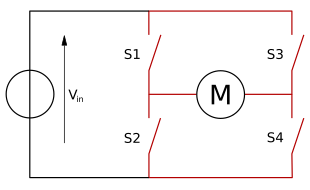
H-bridges have 4 switches, and depending on how you attach the first two leads (transistor switches) to power or ground, the motor it controls will move either forward, backward, or stop.
Here's a video of me pulling pin 1 from ground to power, and pin 2 from power to ground.
You can hear my brother being completely unprofessional and ruining my video.
Finally, I move on to a sound device. I've got to use it to create a short melody. Hopefully I can add sound effects to my hacked toy.
The piezo sounder is great for making annoying retro beep noises.
Our microcontrollers can easily control them with just two connections, and a program statement of "tone([pin#], [frequency], [tone duration]);"
Obviously, I've got a program that runs this statement several times with specified notes and durations.
Next, I use a light sensor to control its pitch, kinda like a theremin. Simple analog input for an analog pitch output.
Yep, that's pretty freaking annoying.
Saturday, January 19, 2013
Using the Microcontroller
The first thing to do this time was to start hacking my robotic toy.

I got a Hexbug.
I tore out its guts and went straight for the motor leads, soldered them to appropriate gauge wires, then attached it to my breadboard.
My motor requires very small voltage, so I used three diodes in series to reduce the 6 volts I was getting from my power supply.
I removed its wheels. Haha.
Next, I needed to learn how to use transistors to control the large voltage of the power supply with the small voltage of the microcontroller. Transistors can be chained in a "Darlington arrangement" to effectively create a more sensitive transistor that controls a larger current.
I managed to use transistors and the microcontroller to light up a holiday light, which requires much more current than an LED.

The two black components are transistors in a Darlington arrangement.
The controller activates the transistor's "base" which allows the larger current through the transistor.
The arrangement I created can be replaced with a specialized transistor component that houses the same arrangement.

Ignore the green wire and small transistor. :(
Then I switch out the light for my Hexbug. I can control the speed of its motor by varying the voltage it receives. The Launchpad allows me to output an analog voltage (0% - 100%) to the resistor, which in turn, sends about the same relative voltage to the motor.
My program cycled between slow and... extra slow.
Thursday, January 17, 2013
Microcontrollers!
Today, I get familiar with the soon-to-be brain of my hacked robots. I will program this MSP430 microcontroller to output or input whatever I want!
The next task was to use one pin on the controller for input, and one for output. The input pin registers "on" when I close its circuit with a push button, and the output pin lights up an LED.
Then I ran a program that lights up multiple LEDs in sequence. My code designates the timing and order that they light up in.
The next task was to use one pin on the controller for input, and one for output. The input pin registers "on" when I close its circuit with a push button, and the output pin lights up an LED.
I give you a brief look at my code here too, but I won't really go into that.
The program's "setup" method begins the program with one light pulsing on and off at an increasing rate, then the main "loop" method runs several LED pulsing commands in sequence to create a scrolling effect like the car KITT from Nightrider.
I reset the program with the reset button on the controller.
Also, there's close up of the microcontroller.
Last was to use the Light Dependent Resistor (LDR) as analog input for the controller, and use that input to output 4 different states, as indicated by the LED pattern. I just cover the LDR with my fingers to vary its input.
Full ambient light - both light
high-medium light - LED1 lights
low-medium light - LED2 lights
low ambient light - none light
Wednesday, January 16, 2013
Electronic Switches
I got behind. Catching up with the rest of the class, I did some fun stuff with relays. Relays are switches powered electronically. They have an electromagnet inside that controls its switch gates, and that magnet gets its own circuit.

Hah, that jumper cable is huge.
The red and yellow lights alternate when I activate the magnet. I know, yellow is super dim.
Next was to have the relay oscillate, in other words, operate itself.
I basically routed the magnet's circuit through the switch gates it controls.
It just buzzes because the relay is switching itself on and off ultra-fast. It's so fast, the lights just look dimmer.
This will destroy the relay pretty quickly though.
What do? ...Capacitor!
A capacitor is basically a super-fast rechargeable battery. The capacitor will soak up the current and release it, over and over, effectively slowing down the alternation of the relay.
The capacitor I used was smaller capacity than what was recommended, so the lights alternate faster than everyone else's. *shrug*
Next is transistors. Finally!
-The heart and soul of electronics.
...OK, maybe not the soul. But still pretty freakin' important!
They have just three nodes: the collector, emitter, and base. The first two relay a current, and the base controls the current. It's similar to a relay switch, except faster, simpler, and cheaper.
Here I control an LED with a transistor that I actuate by completing a circuit with my finger.
The great thing about them is that a tiny current can control the flow of a large one.
Oh, and finally I built a robot from those parts I showed earlier. It's a simple "Boxbot," and it's currently just an r/c toy.
OK, I did not want this video in vertical, but that controller is HUGE, and I was my own camera man. Deal with it.
Thursday, January 10, 2013
Potentiometers and Switches
Today I played with more electronics and inventoried my parts for robot building.
I learned that components require optimal current to keep their lifespan healthy. For instance, the LED runs best at about 0.02 amps, so with a 5V power adapter, it should have 5/0.02 (Ohm's law) resistance in its circuit. Too much current will damage the component, reducing its lifespan.


I learned that components require optimal current to keep their lifespan healthy. For instance, the LED runs best at about 0.02 amps, so with a 5V power adapter, it should have 5/0.02 (Ohm's law) resistance in its circuit. Too much current will damage the component, reducing its lifespan.

This is a photoresistor - it varies its resistance based on how much light it detects.

This circuit has 250 ohms of resistors, resulting in less current than is optimal for the LED.
The potentiometer is simply a resistor with a knob that varies its resistance. If you couple a potentiometer with an optimal resistor, you emulate a house light fixture with an analogue control. The optimal resistor prevents the resistance from ever going too low!

A neat double switch circuit that emulates your average hall light switches. Flip either switch, and the light will toggle!
Soon I will build a simple robot from my newly acquired VEX parts.

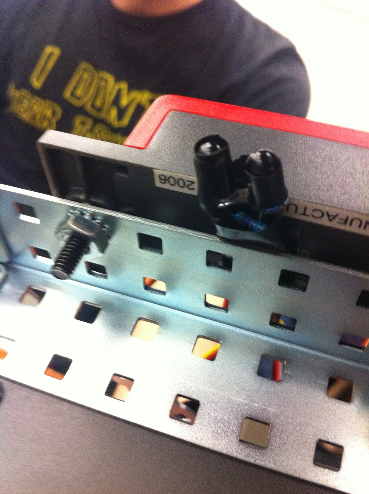
Here's a shot of my new parts (that got used last season and had ruined inventory)!
I had to re-inventory them and discard all the extra parts.
Using a breadboard and multimeter
For the first item on our agenda, I was given the opportunity to play with a breadboard using resistors, LEDs, and my custom power supply. LEDs light when completing the circuit, and resistors add resistance to the circuit, restricting current provided by the power source. The greater the current received by the LED, the brighter it lights.

A breadboard circuit with two resistors, three LEDs, and power.
Next was to test batteries using a multimeter. The "1.5 V" batteries measure higher than 1.5 V on the multimeter when they're new, and older ones register much lower voltages.

The two multimeter nodes held above a battery.
Just as previously understood, our power outlets provide a ~120V output.

Multimeter testing the alternating current voltage of the outlet.
The last item was to compare the voltage output of an old unregulated power adapter with a modern regulated adapter. The regulated adapter automatically adjusts the output based on how much resistance is in the circuit, so the voltage is consistent. We found that this was not the case for the unregulated adapter, as putting the wrong amount of resistance in its circuit would result in burning out the resistor.
Fortunately for me, I've got a modern power adapter.
Fortunately for me, I've got a modern power adapter.
Wednesday, January 9, 2013
Building and Testing a 5V power supply
This was my first project in ELEC10. The primary objective was simply to get some practice with basic electronics tools and procedures.
The first task was quite basic, just soldering components into a breadboard. The trick was to heat the copper pads sufficiently before applying the solder, so it would flow down and stick to the pad.

Small bread board with transistors and capacitors soldered into random locations.
The next task was tricky because it required soldering two loose wires together without twisting.

Six separate wires were stripped and soldered together into a circle with heat shrink to cover the metal.
The last task was even more difficult, but I have not yet finished it. I stripped the surface insulation (black) from the two wires inside and then stripped a small length from the wires. The black insulation was really tough to sever without damaging the wires.
Next, I will solder the two wires to their respective leads pictured below, then shrink wrap one lead so the two don't make contact.

The power supply with the output end cut off. The two wires are to be soldered to the leads, and the black shrink wrap slid down over the white wire's solder.
Subscribe to:
Comments (Atom)